Power generation and transmission

📝 Mini-cours GRATUIT

Alternating current (ac) generators

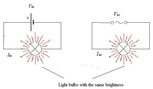
Alternating current $(ac)$ electricity is the most convenient to generate, transform and transmit.

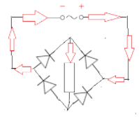
  • Electricity for commercial and home use comes mainly from generators that involve a coil rotating in a magnetic field.
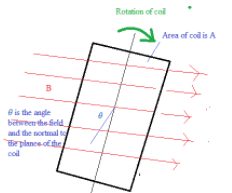
    $\Phi=\mathrm{BA} \cos \theta$
    If $\omega$ is angular frequency, $\theta=\omega t$
    $\Phi=\mathrm{BA} \cos \omega \mathrm{t}$
    $\varepsilon=-\Delta \Phi / \Delta \mathrm{t}=\omega \mathrm{BA} \sin \omega \mathrm{t}$
  • This shows:
    • The flux, and emf oscillate with the same frequency   
    • The flux and the voltage are out of phase by $\pi/2$
    • The induced emf is proportional to the angular frequency. If angular frequency is doubled the peak voltage is also doubled.
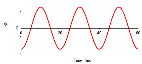
  • In the example below, the coil rotates with a period of $\rm 20~ms$.
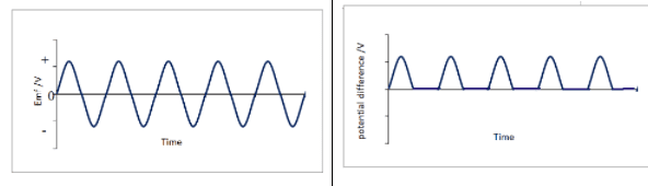
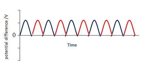
  • The corresponding induced emf and current in a domestic supply are shown below.
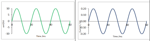
  • The following should be noted:
    • The flux, emf and current oscillate with the same frequency.
    • The current and the voltage are in phase
    • When the flux is zero the rate of change of flux has maximum magnitude and so has the emf and current. 
    • When the flux has maximum magnitude the rate of change of flux is zero and so is the emf and current.

Average power and root mean square (rms) values of current and voltage

  • Consider the dc and ac circuits below:

    If the bulbs have the same brightness they are working at the same power.
    $\rm P=V_{d c} I_{d c}=V_{a c} I_{a c}$
  • In an ac circuit power is not constant in time. It has a maximum value $\rm P_{\max }$ given by the product of the peak voltage and peak current: $\rm P_{\max }=V_{0} I_{0}$ and a minimum value of $0 \mathrm{~V}$.
  • The average power $\rm =½ V_{0} I_{0}=V_{a c} I_{a c}$
    • $\rm I_{a c}=\dfrac{1}{\sqrt 2} I_{0}=I_{r m s}$
    • $\rm V_{a c}=\dfrac{1}{\sqrt 2} V_{0}=I_{r m s}$
  • The rms current $\rm \left(I_{m m s}\right)$ is the current which in a dc circuit would give the same power dissipation as the average power in the ac circuit.
    The rms voltage $\rm \left(V_{\text {rss }}\right)$ is the voltage which in a dc circuit would give the same power dissipation as the average power in the ac circuit
    In the graphs above:
    • $\rm V_{0}=10.0 \mathrm{kV}$ and $\rm V_{tms}=10.0 / \dfrac{1}{\sqrt{2}} \mathrm{kV}=7.07~ \mathrm{kV}$
    • $\rm I_{0}=0.20 \mathrm{kA}$ and $\rm I_{ms}=\dfrac{1}{\sqrt{2}} 0.20 ~kV=0.14~ \mathrm{kA}$
  • The resistance $\rm (R)$ of the circuit $=10 / 0.20=7.07 / 0.14=50 \Omega$.
  • The average power dissipated in ac circuits can be calculated from rms quantities using the same formula as dc circuits:
    $\rm P_{\text {avcrage }}=V_{\text {rms }} I_{\text {mss }}=V^2{_{rms}} / R=I^2{_{rms}} ~R$
    $\mathrm{rms}=$ root mean square so it is the square root of the mean of the $\mathrm{I}^{2}$ or $\mathrm{V}^{2}$ values.
    It is the most appropriate average to take when the quantity is oscillating in positive and negative directions with a mean of zero.

Ideal Transformers

  • Consider two coils: a primary and a secondary with Np and Ns turns of wire respectively
  • An alternating voltage $\varepsilon p$ is applied to the primary coil which produces a varying magnetic field in the core. This varying magnetic field also passes through the secondary coil. The changing flux linkage induces a secondary emf $\varepsilon$.
    $\varepsilon_{p}=-\rm \Delta \Phi_{p} / \Delta t=-N_{p} \Delta B A / \Delta t$
    $\varepsilon_{p} /\rm N_{p}=-\Delta B A / \Delta t$
    $\varepsilon_{p} / \rm N_{p}=\varepsilon_{S} / N_{S}$
    $\varepsilon_{p} / \rm \varepsilon_{S}=N_{p} / N_{S}$
    ––––––––––––––
    $\rm \varepsilon_{S}=-\Delta \Phi_{s} / \Delta t=-N_{S} \Delta B A / \Delta t$
    $\rm \varepsilon_{S} / N_{S}=-\Delta B A / \Delta t$
  • For an ideal transformer with $100 \%$ efficiency the power in the secondary coil equals that in the primary coil and so $\rm \varepsilon_{\mathrm{p}} I_{\mathrm{p}}=\varepsilon_{s} I_{\mathrm{s}}$.
    $\rm \varepsilon_{\mathrm{p}} / \varepsilon_{\mathrm{s}}=I_{\mathrm{s}} / I_{\mathrm{p}}=N_{p} / N_{S}$
    In the example above $\rm N_{p}=3$ and $\rm N_{S}=6$ so
    $\rm \varepsilon_{\mathrm{p}} / \varepsilon_{\mathrm{s}}=I_{\mathrm{s}} / I_{\mathrm{p}}=2$
  • Transformers can only be used with alternating current and do not change the frequency of the ac current.
    The symbol for a transformer:

Power losses with non-ideal transformers

  • Power losses with non-ideal transformers include:
    • Heat losses in the resistance of the coils.
    • Losses due to unwanted eddy currents induced in the iron core. These currents can be reduced by laminating the core into individually insulated thin strips.
    • Losses due to hysteresis which make the iron core warm up as a result of the continued cycle of changes to its magnetism.
    • Not all magnetic flux produced by the primary coil links with the secondary coil.

Power losses in transmission

  • Transformers are used to reduce power losses in cables during the transmission of electricity.
    If the cables have a resistance $\rm (R)$ the power lost $\rm \left(P_{\text {lost }}\right): P_{\text {lost }}=I^{2} R$.
    This loss is minimised if the current is as small as possible.
    As $\rm P=VI$ for a given power transmission $\rm V$ must be large.
  • A power station produces a large amount of power; the voltage is stepped up by transformers before transmission and then stepped-down near the place of use to a suitable value before supplying to consumers at suitable smaller voltages.

Worked Example

A power station produces $\rm 800 ~MW$.
Compare the energy losses when this is transmitted at $\rm V_{1}=200 ~kV$ and $\rm V_{2}=50~kV$.

Solution

$\rm\scriptstyle P$ $=$ $\rm\scriptstyle V I$ for $\rm \scriptstyle V_{1}$
$\scriptstyle 800~ \times~ 10^{6}$ $=$ $\scriptstyle 200~ \times ~10^{3} \mathrm{I}_{1}$
$\scriptstyle \mathrm{I}_{1}$ $=$ $\scriptstyle 800~ \times~ 10^{6} / 200~ \times~ 10^{3}$
$\scriptstyle \rm I_1$ $=$ $\scriptstyle 4.00~ \times~ 10^{3}$
$\rm \scriptstyle P_{\text {lost }}$ $=$ $\rm\scriptstyle I^{2} R$
$\scriptstyle\rm P^{lost}_1$ $=$ $\scriptstyle\rm(4.00~ \times ~10^{3})^{2} R$
$\rm \frac{P^{lost}_2}{P^{lost}_1} =\frac{(16.0~ \times ~10^{3})^{2} R}{(4.00 \times 10^{3})^{2} R}$
$=$ $\scriptstyle (4)^{2}$ $=$ $\scriptstyle 16$

for $\rm\scriptstyle V_{2}$
$\scriptstyle 800~ \times ~10^{6}$ $=$ $\scriptstyle 50~ \times~ 10^{3} \mathrm{I}_{2}$
$\rm \scriptstyle I_{2}$ $=$ $\scriptstyle 800~ \times~ 10^{6} / 50~ \times~ 10^{3}$
$=$ $\scriptstyle 1.60~ \times~ 10^{3}$
$\rm \scriptstyle P^{lost}_2$ $=$ $\rm \scriptstyle (16.0~ \times~ 10^{3})^{2} R$

Stepping the voltage up by a factor of $4$ reduces the power losses by factor by $16$.

Diode bridges

  • Alternating current(ac) is the easiest to generate, transform and transmit but direct current (dc) is needed for many electrical devices.  
  • The conversion from ac into dc is called rectification which uses diodes.
    An ideal diode allows current to flow in only one direction.
  • It has negligible resistance in the forward direction and infinite resistance in the reverse direction.

The potential difference-current graph for a diode

The symbol for a diode:

Half-wave rectification

Consider the circuit below:

  • The graph of the emf produced by the ac source and the potential difference across the resistor are shown.
  • This half-wave rectification produced by a single diode converts ac into a pulsating dc current.
    The electrical energy in the negative cycle of the ac is not available for use.

Full-wave rectification

  • A diode bridge of four diodes uses all the electrical energy that is available during a complete cycle.
  • The current always passes through the resistor in the same direction for an alternating source.
  • In one half of the half of the cycle, current flows in the direction of the blue arrows and in the other half in the direction of the red arrows.
  • The voltage across the resistor varies as follows. This is full wave rectification.
  • The following points should be noted:
    • Diodes on parallel sides point in the same directions.
    • Diodes point in opposite directions at the junction where the $\rm AC$ current enters and leaves the bridge.
      Only two diodes conduct during each half-cycle
  • The output of the diode bridge rectifier can be made smoother by adding a capacitor in parallel to the load. This is covered in more detail in section $11.3$. 

FAQ