Heating effect of electric currents

📝 Mini-cours GRATUIT

Heating effect of electric currents

One of the most important applications of electricity is to produce heat and light.

Electric Circuits

  • The total work done per unit charge by the battery is called the emf ε
  • Emf is measured in joules per coulomb = the volt.
  • To measure the current passing through a resistor an ammeter is placed in series with the resistor.
  • The current $\rm I$ is the same through all the components.
  • The potential difference across a resistor is measured using a voltmeter in parallel to the resistor.

Series Circuits

The current is the same in both resistors.

The battery gives each unit of charge $\varepsilon$ units of energy. This is the emf of the battery.
The resistors dissipate $\rm V_1$ and $\rm V_2$ units of energy for each unit of charge:

$\rm \in ~= V_1 + V_2$

Parallel Circuits

  • In a parallel circuit the current splits into $\rm I_1$ and $\rm I_2$. Due to the conservation of charge:
    $\rm I = I_1 + I_2$
  • The battery gives each unit of charge units of energy. This energy is dissipated through one or other of the resistors:
    $\rm \in~= V_1 = V_2$

Kirchhoff’s Circuit Laws :
The conservation of electric charge and the conservation of energy lead to Kirchoff’s circuit laws

  • The current entering a junction is equal to the current leaving a junction:
    $\rm I_{in} = I_{out}$
    This can also be expressed
    $\rm \Sigma I = 0$ (junction)
    (with $\rm I_{in}$ positive and $\rm I_{out}$ negative)
  • $\rm Σ~V = 0$ (loop)
    $\text{Energy in} = \text{energy out}$
    $\rm\Sigma(emf) = \Sigma (IR)$

Worked Example

Example 1

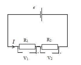
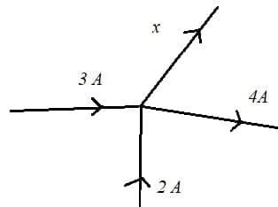
Deduce the current x in the part of the circuit shown.

Solution
$\color{red}{\rm I_{in} = 3 + 2}$
$\color{red}{\rm I_{out} = 4 + \cal x}$
$\color{red}{3 + 2 = 4 + x}$
$\color{red}{x = 3 + 2 - 4 = 1~\rm A}$

Example 2

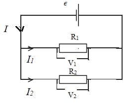
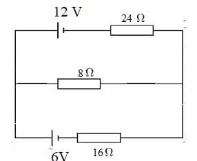
Find the currents in the following circuit.

Solution
Label the junctions and show the currents with arrows.

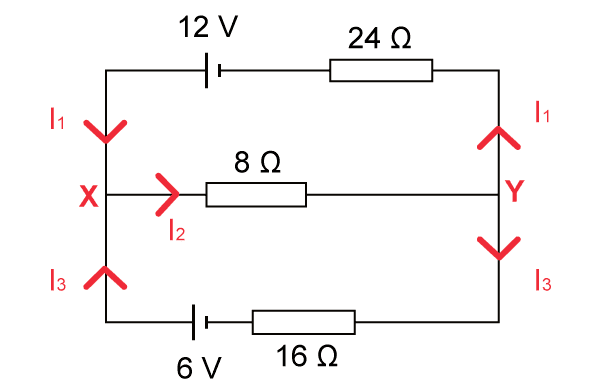
There are $3$ different currents: $3$ equations are needed to solve the problem:
$\color{red}{\bullet}$ Use $\color{red}{\rm\Sigma I = 0}$ (junction) or $\color{red}{\rm I_{in} = I_{out}}$

At junction $\bf X$: $\color{red}{\rm I_1 + I_3 = I_2}$
At junction $\bf Y$: $\color{red}{\rm I_2 = I_3 + I_1}$
The same equation applies at both junctions.

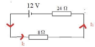
We can obtain a second equation by considering the top loop.
Applying Energy in = energy out: $\color{red}{\bf \Sigma(emf) = \Sigma(IR)}$
$\color{red}{\rm 12 = 8 ~I_2 + 24 ~I_1}$

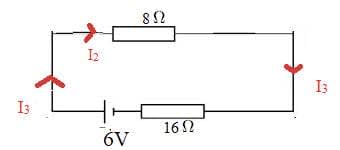
And a third equation by considering the lower loop:
$\color{red}{\rm 6 = 8~ I_2 + 16~ I_3}$

We now need to solve the three equations:

$\color{red}{\left\{\begin{array}{ll}\rm I_1 + I_3 = I_2\\
\rm 12 = 8 ~I_2 + 24~ I_1\\
\rm 6 = 8~I_2 + 16 ~I_3\end{array}\right.}$

$\color{red}{\left\{\begin{array}{ll}\rm I_3 = I_2 - I_1\\
\rm 12 = 8 ~I_2 + 24~ I_1\\
\rm 6 = 8 ~I_2 + 16~ ( I_2 - I_1 ) = 24 ~I_2 - 16~ I_1\end{array}\right.}$

$\color{red}{\left\{\begin{array}{ll}\rm I_3 = I_2 - I_1\\
\rm 12 = 8 ~I_2 + 24~ I_1\\
\rm 3 = 12~ I_2 - 8~I_1 \end{array}\right.}$

$\color{red}{\left\{\begin{array}{ll}\rm I_3 = I_2 - I_1\\
\rm 12 = 8 ~I_2 + 24~ I_1\\
\rm 12~ I_2 = 3 + 8~ I_1 \end{array}\right.}$

$\color{red}{\left\{\begin{array}{ll}\rm I_3 = I_2 - I_1\\
\rm 12 = 8 ~I_2 + 24~ I_1\\
\rm I_2 = \dfrac{1}{4} + \dfrac{2}{3} I_1 \end{array}\right.}$

$\color{red}{\left\{\begin{array}{ll}\rm I_3 = I_2 - I_1\\
\rm 12 = 8 \left(\dfrac{1}{4} + \dfrac{2}{3}~I_1 \right) + 24~ I_1\\
\rm I_2 = \dfrac{1}{4} + \dfrac{2}{3} I_1 \end{array}\right.}$

$\color{red}{\left\{\begin{array}{ll}\rm I_3 = I_2 - I_1\\
\rm 12 = 2 + \dfrac{16}{3}~ I_1 + \dfrac{72}{3}~ I_1\\
\rm I_2 = \dfrac{1}{4} + \dfrac{2}{3} I_1 \end{array}\right.}$

$\color{red}{\left\{\begin{array}{ll}\rm I_3 = I_2 - I_1\\
\rm 10 = \dfrac{88}{3}~ I_1 \\
\rm I_2 = \dfrac{1}{4} + \dfrac{2}{3} I_1 \end{array}\right.}$

$\color{red}{\left\{\begin{array}{ll}\rm I_3 = I_2 - I_1\\
\rm I_1 = \dfrac{30}{88} = 0.34~A \\
\rm I_2 = \dfrac{1}{4} + \dfrac{2}{3} \times (0.34) = 0.48~A \end{array}\right.}$

$\color{red}{\left\{\begin{array}{ll}\bf I_1 = 0.34~A \\
\bf I_2 = 0.48~A\\
\bf I_3 = 0.48 - 0.34 = 0.14~A\end{array}\right.}$

Resistance

  • Ohm’s law states that the current flowing through a piece of metal is proportional to the potential difference across it at constant temperature.
    $\rm V ~\infty ~I$ (if temperature is constant)
  • A device with constant resistance (in other words an ohmic device) is called a resistor.
  • The resistance $\rm R$ of a component is the ratio of the potential difference $\rm V$ across it divided by the current through it, $\rm I$, $\rm R = V/I$.
    The unit of resistance is the ohm: $\rm 1~ \Omega = V.A^{-1}$.
  • Conductors that do not obey Ohm’s law are call non-ohmic.

The $\rm I−V$ characteristics of non-ohmic conductor such as a filament lamp.

The resistance at $\rm X = 2.0/2.0 = 1.0~\Omega$
The resistance at $\rm Y = 5.0/3.0 = 1.7~\Omega$

  • The resistance of a thermistor decreases as the temperature increases.
  • The resistance of a LDR (light-dependent resistor) decreases as the intensity of light incident on the device increases.

Resistivity

  • For a conductor of uniform cross-sectional area, $\rm A$, and length $\rm L$:
    $\rm R = \rho L/A$
    $\rho$ is the resistivity and depends on the temperature and the material of the conductor.
    $\rho$ has units $\rm \Omega.m^{-1}$

Resistors in Series and Parallel

Series circuit

$\rm \varepsilon = I ~R_{\text {total }}$
$\rm \varepsilon = V_{I}+V_{2}=I ~R_{1}+I ~R_{2}$
$\rm I~ R_{total} = I~ R_{I} + I~R_{2}$
$\rm R_{total} = R_{I} + R_{2}$

Parallel circuit

$\rm \varepsilon= I_{total}$
$\rm I=\varepsilon / R_{total}$
$\rm I=I_{l} + I_{2}$
$\rm \varepsilon / R_{total} = V_{1} / R_{l} + V_{2} / R_{2}$
$\rm \varepsilon / R_{total} = \varepsilon / R_{1} + \varepsilon / R_{2}$
$\rm 1 / R_{total} = 1 / R_{I} + 1 / R_{2}$

  • An ideal ammeter does not change the resistance of the circuit. As it is connected in series it has zero resistance.
  • An ideal voltmeter does not change the resistance of the circuit or take any current. As it is connected in parallel it has infinite resistance.

Electric Power

  • Power(P) is the rate at which energy is dissipated.
  • The amount of charge that gets transferred across the resistor in time $t$ is $\rm Q = I\cal t$.
    The work required to move a charge $\rm Q$ across a potential difference $\rm V$ is $\rm Q_V$.
    $\rm \text{Energy dissipated} = Q_V = VI\cal t$
    $\rm Power =Energy /time = Vit/ \mathcal t = VI$
    $\rm P = VI$
  • Using the definition of resistance $\rm R = VI$:
    $\rm P = VI = I^2~R = V^2/R$

Potential divider circuit

  • The circuit on the left is called a potential divider circuit. The point where the slider S touches the resistor determines the output voltage.
  • When the slider is at the far left $(x = 0)$ the output voltage = 0
    When the slider is at the far right $(x = l)$ the output voltage is a maximum. This is $\varepsilon$ if the battery has zero internal resistance or $\varepsilon − \mathrm Ir$ otherwise (see later $5.3$).
  • More generally the resistor divides the emf $\varepsilon$ of the battery: $\mathrm{V_{out}} = \varepsilon x/ l$
  • A variable potential divider is an effective way to produce a variable power supply.

FAQ