Capacitance

📝 Mini-cours GRATUIT

Capacitance

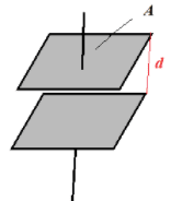
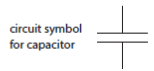
Capacitors can be used to store charge and electrical energy.

  • Capacitance $\bf (C)$ is the electric charge $\rm (Q)$ that can be stored on a body per unit voltage:
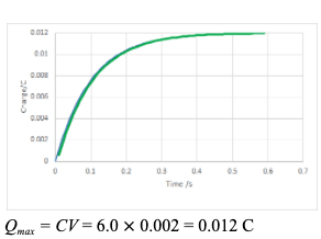
    $\bf C = Q / V$ The unit of capacitance is the farad $\rm (1~F=1=CV^{-1})$
  • For a body of capacitance C and voltage V the charge that can be stored is $\rm Q = CV$.

Dielectric materials

  • A capacitor is any arrangement of two conductors separated by insulating material (or a vacuum). It is capable of storing electric charge and energy.
  • A parallel plate capacitor has two identical parallel plates of area $A$, separated by a distance $d$:


  • A charge builds up on the plates: positive charge $q$ on one plate and an equal and opposite charge $-q$ on the other when the capacitor is connected to a battery and an electric field is produced between the parallel plates when they are charged.
    For the parallel plate capacitor: $\mathrm C=\varepsilon / A d$
    $A$ is the area of one of the plates, $d$ the separation of the plates and $\varepsilon$ the permittivity of the medium between the plates.
    For a vacuum $\varepsilon=\varepsilon_{0}=8.85 \times 10^{-12} \mathrm{~F} \mathrm{~m}^{-1}$.
    A dielectric material can be placed between the plates to increase the capacitance compared to a vacuum. Different materials have different values of $\varepsilon . \varepsilon>\varepsilon_{0}$ as the induced charge separation across the dielectric increases the capacitance.

    • The material of the dielectric is polarized by the positive and negative plates. This produces an electric field which opposes that the plates. The dielectric reduces the net electric field: $\rm E_{net}=\Delta V/\mathcal d$
    This reduces $\rm \Delta V$ as $d$ is unchanged
    And increases the capacitance: $\rm C = Q/V$

Capacitors in parallel

Capacitors in parallel: $\bf C_{parallel}$:

  • Two capacitors of capacitance $\rm C_{1}$ and $\rm C_{2}$ are connected in parallel to a source of potential difference $\rm V$.
    $q_{1}=\rm C_{1} V$ $\quad q_2 = \rm C_2V$ $\quad q =\rm C_{parallel}V$
    $\text{Total charge} ~(q)=q_1 + q_2~(\rm C_1 +C_{2}) V$
    $\rm C_{\text {parallel }}=(C_{1}+C_{2})$
  • Let the total capacitance of the parallel combination be $\rm C_{\text {parallel }}$.
    $q=\rm C_{\text {parallel }} V$

Capacitors in series

Capacitors in series: $\mathrm{C}_{\text {series }}$

  • Two capacitors of capacitance $\rm C_{1}$ and $\rm C_{2}$ connected in series.
    The charge on each capacitor is the same.
    $\mathrm V_{1}=q / \mathrm C_{1} \quad \mathrm V_{2}=q / \rm C_{2}$
    $\rm V=V_{1}+V_{2}$
    $q / \mathrm C_{1}+q / \mathrm C_{2}=q / \rm C_{\text {series }}$
    Dividing by $q$ gives:
    $\rm I / C_{1}+1 / C_{2}=1 / C_{\text {series }}$
  • The total capacitance of the series combination: $\rm C_{\text {series}}$.
    $\mathrm V=q / \rm C_{\text {series }}$
  • The equations for capacitors in series and parallel should be contrasted with those for resistors.
    Capacitors Resistors
    In series In parallel In series In parallel
    $\scriptstyle\rm 1/C_{series}$ $=$ $\scriptstyle\rm 1/C_1+1/C_2$ $\scriptstyle\rm C_{parallel}$ $=$ $\rm\scriptstyle C_1+C_2$ $\scriptstyle\rm R_{series}$ $=$ $\scriptstyle\rm R_1 + R_2$ $\scriptstyle\rm 1/R_{parallel}$ $=$ $\rm\scriptstyle 1/R_1+1/R_2$

Energy stored in a charged capacitor

    • A charged capacitor stores electrical energy.
    • The energy needed $\rm \Delta E$ to add charge $\rm \Delta Q$ to a capacitor $\rm =V \Delta Q$
      The total energy stored = area under the $\rm V/Qgraph$.
      As this is a triangle:
      • $\rm E=½~ V Q$
      • $\rm E=½~ C V^{2}$ $\rm \quad(Q=C V)$

Charging a capacitor

  • A capacitor can be charged and discharged using the circuit shown. When the switch is at $\rm A$ the capacitor is charged when at $\rm B$ it is discharged.
  • The potential difference of the capacitor increases to the potential difference of the battery $\varepsilon$. 
  • As the potential of the capacitor increases the potential difference between the battery and the capacitor decreases and so does the current.
  • The rate of voltage increase; depends on the product of the resistance and capacitance: $\rm RC$.
    • The larger the value of $\rm R$ the smaller the charging current.
    • The larger the value of $\rm C$ the smaller the voltage of the capacitor for a given charge.
  • The larger $\rm R C$ the slower the rate at the capacitor is charged:
    $\mathrm{V}_{\mathrm{c}}=\varepsilon\left(1-\mathrm{e}^{-\mathrm{t} / R C}\right)$
  • The current varies with time:
    $\rm I=(\varepsilon-V c) / R$
    $\rm I=\varepsilon / R e^{-t \mathrm{RC}}=\mathrm{I}_{0} \mathrm{e}^{-/ R C}$ where $\rm I_{0}$ is the maximum current.
  • The quantity $\rm R C$ is called the time constant and is denoted by the symbol $\tau:\tau =R C$
  • As $q=\rm C V$ the graph showing the variation of charge with time has the same shape as that of potential difference.
  • Note the current is the slope of the charge time graph; so is a maximum at the $\rm t=0$ and falls to $0$ as the capacitor is fully charged.

Discharging a capacitor: V and Q 

  • A charged capacitor now is a power source. At any instant, the current $\rm I$ and the pd $\rm V_{\mathrm{C}}$ across the capacitor are related by $\rm V_{\mathrm{C}}=I R$ But $\rm V_{\mathrm{C}}$ and $\rm I$ change with time.
  • The charge decreases with time according to equation:
    $\rm Q=\mathrm{Q}_{0} \mathrm{e}^{-t / R C}$
  • The voltage across the capacitor is similarly given by $\rm V=Q / C \quad V_{o}=Q_{d} / C$
    $\rm V=V_{0} \mathrm{e}^{-t R C}$ where $\rm V_{0}$ is the initial voltage.
  • The electric current can be obtained from the gradient of the charge time graph.
    $\rm I=I_{0} \mathrm{e}^{-t/ R C}$
  • It follows the same pattern as the current for the charging process but is in reverse direction.

The time constant τ

  • The time constant $\bf \tau = RC$ determines the time scale for the discharge of the capacitor: a large time constant means that it will take a long time for the charge on the plates to decrease appreciably.
  • More precisely, after a time $t=\tau$ the charge will be:
    $q=q_{0} \mathrm{e}^{-t / \tau} = q_{0} e \approx 0.37 ~q_{0}$
    The time constant is the time after which the charge decreases to about $37 \%$ of its initial value.
  • Discharge curves are exponential, like those for radioactive decay and we can find the 'half-life' $\rm T_{½}$ :
    $q=½ q_{0}~ \mathrm{t}:$
    $q=½ q_{0} = q_{0} \rm e^{-T}{_ {½}}^{/ \tau}$
    $\rm ½=e^{-T}{_ {½}}^{/ \tau}$
    $\ln 2=T_{½} / \tau$
    $T_{½}=\ln 2 \tau$
  • The unit of $\rm RC =\Omega F$ $\quad$ $\rm \Omega=VA^{-1}(R=V / I)$ $\quad \rm F = CV^{-1}$ $\rm (C=Q / V)$
    $\rm =VA^{-1 \times} CV^{-1}$
    $\rm =C ~A^{-1}$ $\quad \rm C = A~s(Q=It)$
    $=\rm A~s~A^{-1}$
    $\rm =s$ as expected for a time constant.

The effect of adding a capacitor to a diode bridge rectification circuit

  • As discussed in section $11.2$ a diode produces a half-way rectification.
  • The waveform can be made smoother if a capacitor is placed in parallel with the resistor.
  • During the first half cycle as the voltage increases to a maximum the capacitor charges.
  • As potential falls the capacitor starts to discharge. The rate of discharge depends on $\rm RC$ the time constant.
  • If $\rm RC$ is sufficiently large the discharge will be slow enough to maintain current and the potential difference across the load resistor.
  • The voltage of the capacitor is topped up during the next half cycle when current can pass through the diode.
  • The small variation is known as the ripple voltage. The ‘ripple’ is reduced with higher capacitance or load resistance.
  • The output of the diode bridge rectifier can be made smoother by adding a capacitor in parallel to the load in the same way.

FAQ